


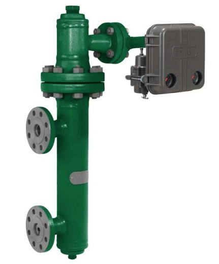
Calibration of Leveltrol in the Field

Preparation:
- Close both primary isolation valves.
- Drain the liquid inside the chamber.
Zero Adjustment:
- Adjust the zero to get a 0% output.
Setup:
- Connect a transparent PVC tube to the drain point as per hookup instructions.
- Fill the tube to the center of the top flange.
Span Adjustment:
- Adjust the specific gravity or span adjustment (for electronic leveltrol).
Check Linearity:
- Fill up to 50% level and check linearity of output.
Calibration of Interface Level Control
- Interface leveltrol deals with two liquids of different specific gravities.
Zero Level (0%): When full of lighter liquid
[ \text{Zero % level} = H \times d ]- (H): Displacer length
- (d): Specific gravity of lighter liquid
Full Level (100%): When full of heavier liquid
[ 100% \text{ level} = H \times D ]- (D): Specific gravity of heavier liquid
Calibration with Water:
- Fill to (H \times d) level with water and adjust zero.
- Fill to (H \times D) level with water and adjust span (specific gravity).
- Check linearity.
Weight Test Calibration of Leveltrol
- Remove the displacer from the torque arm.
- Apply an equivalent weight on the torque arm equal to the displacer weight to adjust zero output.
- For Span:
- Volume (V = \pi r^2 h)
- Loss in weight = Weight of float – (Volume × density of liquid)
- Span weight = Weight of float – Loss in weight
- Apply weight equal to Span weight on torque arm and adjust span to get 100% output.
- Check linearity by applying average of the two weights.
Common Issues
- If displacer falls down while in line: Output will be at maximum.
- If displacer has a hole: Output will be at minimum.
Use of Suppression and Elevation
- Applied in level measurement when:
- Transmitters are not mounted at the same level.
- Wet leg is present (condensable vapors in the impulse line).
Limitations of Leveltrol
- Cannot be used for displacer lengths greater than 72 inches.
Commissioning a Differential Pressure (D.P.) Transmitter in a Pressurized Vessel
- Close both isolation valves.
- Vent the High Pressure (H.P.) side.
- Fill the transmitter with sealing liquid.
- Open the Low Pressure (L.P.) side vent valve.
- Adjust zero using the suppression spring.
- Close the L.P. vent valve.
- Open both isolation valves.
Checking Zero of a Level D.P. Transmitter While Inline
- Close both isolation valves.
- Open vent valves on L.P. leg and drain H.P. leg.
- Check and adjust zero if necessary.
Zero Suppression:
- Used when the transmitter is installed below the tank’s zero level.
- Because the transmitter senses additional hydrostatic pressure from the liquid column above it, it reads a pressure even when the tank is empty.
- Zero suppression adjusts the output to ignore this extra pressure, ensuring the transmitter outputs the correct minimum signal (usually 4 mA) when the tank is actually empty.
Zero Elevation:
- Used when the transmitter is installed above the tank’s zero level, or when a wet leg (a liquid-filled capillary line) is used on the low-pressure side.
- In this case, the transmitter senses less pressure than the actual level, so the zero point must be “elevated” (offset upward) to ensure the instrument reads zero level correctly.
- This adjustment ensures the transmitter outputs the correct minimum signal when the tank level is truly at zero.
Working Principle of an Enraf Level Gauge
- Uses a servo-powered null-balance technique with a displacer as a continuous level-sensing element.
- The displacer (denser than the measured liquid) is suspended by a wire attached to a drum.
- A two-phase servo motor controlled by a capacitive balance system winds or unwinds the wire to balance the tension against the buoyant force on the displacer.
- Capacitive sensors detect changes in level by measuring differences in capacitance caused by the movement of a sensing rod.
- An electronic circuit detects and integrates these changes.
- The servomotor’s rotation alters a voltage pattern transmitted to a remote indicator, which drives a counter to display the level variation continuously