




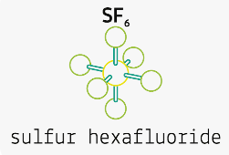
SF? density gauge calibration
must account for temperature variations. Unlike standard pressure gauges,
density gauges use temperature compensation to reflect the true mass of the gas
per volume. This prevents false alarms triggered by ambient temperature
fluctuations.
The following structured
technical breakdown outlines the end-to-end testing methods, step-by-step
procedures, and common errors to watch for during the calibration process.
1. Testing Methods &
Principles
A. Temperature Compensation
Verification
Because SF? gas pressure
fluctuates drastically with ambient temperature variations, density gauges use
an internal mechanical bimetal strip or an electronic sensor matrix to offset
temperature errors. Testing methods rely on converting all test measurements to
a reference baseline of 20 °C absolute pressure.
B. Contact Actuation Measurement
This method tests the point
where electrical microswitches trigger protection schemes. A testing device
applies dynamic pressure changes to capture:
• Alarm Level: First-stage
warning signaling minor gas loss; the equipment remains in service.
• Lockout Level: Second-stage
safety trip that freezes breaker operations to prevent catastrophic arc
failures when insulation density drops below safe operating limits.
2. Step-by-Step Calibration
Procedure
Step 1: Isolation and Safety
Lockout
Isolate the density gauge or
relay from the live Gas Insulated Switchgear (GIS) or Ring Main Unit (RMU)
using the localized block-and-bleed valve manifold. Ensure the electrical
contact circuits are safely disconnected and tagged out.
Step 2: Visual Inspection
Examine the physical body for
structural cracks, corrosion on gas terminals, and signs of oily residue that
indicate seal degradation. Check electrical terminal contacts for burn marks or
loose wiring.
Step 3: Equipment Connection
Secure the density gauge onto a
dedicated SF? density relay test bench. Connect the high-precision pressure
calibrator, a regulated standard gas/air pressure source, and link the contact
pins to a digital multimeter or the test set's input terminals. Ensure all gas
couplings are fully sealed with zero leakage.
Step 4: Multi-Point Reference
Testing
Slowly sweep the pressure upward
and downward across the full scale of the gauge. Apply at least 5 ascending and
5 descending reference pressure points. Record the precise pressure readings
displayed on the gauge at each interval. [1, 2]
Step 5: Data Comparison &
Tolerance Mapping
Convert all logged gauge
readings to the 20 °C equivalent value based on the current ambient
temperature. Compare these values against the reference standard gauge. Verify
that deviations fall within permissible device tolerances: [1, 2]
Device Type Typical Permissible
Accuracy
Mechanical Density Gauge ±1.5%
Full Scale
Density Relay ±1.0% Full Scale
Electronic Density Monitor ±0.5%
Full Scale
Step 6: Parameter Adjustment
If values fall outside standard
tolerances, adjust the gauge using the manufacturer’s adjustment points. For
mechanical units, turn the internal calibration micro-screws. For smart
electronic monitors, update calibration offsets via vendor-specific software.
[1]
Step 7: Alarm & Lockout
Contact Verification
Simulate slow gas leaks and gas
refills to test contact response points. Measure the exact pressure at which
the alarm and lockout microswitches open or close. Confirm that values match
the nameplate trip criteria and that the signal contact remains stable. [1]
Step 8: Comprehensive
Documentation
Generate a certified calibration
record documenting:
• Serial numbers and test dates
• Reference standards used
(traceable data)
• As-Found and As-Left pressure
values
• Ambient temperature during
calibration
• Final signature confirming
pass/fail status
3. Common Calibration Errors
• Ignoring Temperature
Stabilization Time: Skipping the mandatory thermal equalization period between
the instrument and the ambient testing room environment introduces major
measurement offsets.
• Using Unverified Reference
Tools: Calibrating a density gauge with a reference gauge that lacks certified,
high-level traceable accuracy creates systemic errors.
• Overlooking Minor Coupling
Leaks: Micro-leaks at testing connections destabilize pressure curves, leading
to flawed test results and incorrect manual adjustments.
• Omitting the Contact Test
Sequence: Verifying the dial face reading while failing to electrically check
the physical relay microswitch operation leaves severe, hidden protection risks
unaddressed.
4. Troubleshooting Calibration
Anomalies
Post-Adjustment Value Drift
• Root Cause: Worn internal
mechanical bimetal linkages or degraded internal sensor elements.
• Solution: Replace the worn
density gauge assembly entirely.
Failure of Alarm Contact to
Actuate
• Root Cause: Corroded
microswitch contacts, faulty terminal blocks, or severed internal circuit
wiring.
• Solution: Clean contacts with
electrical contact cleaner or swap out defective microswitch relays.
Erratic or Non-Repeatable Test
Results
• Root Cause: Loose physical
connections on the test bench or mechanical binding within the gauge pointer
mechanism.
• Solution: Tighten all
analytical gas fittings and visually verify that the pointer moves smoothly
without sticking.